All electrical connections should only be made only by individuals who are qualified to install electrical appliances with hard wiring design.
The Following instructions apply to the these LakeAir products.
LakeAir Products use several different types of Blowers and Motors. The majority of our products use reverse curve blowers because this blower is adept at puling air through a filtering system. Many of our reverse curve blowers need to be connected to a potentiometer to operate.
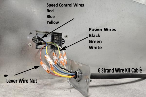
Products with blowers that require potentiometers and are designed for speed control to be mounted at a wall switch have 6 wires available at the power junction box. Each of these wires must be connected for the unit to work properly.
3 of these wires hook directly the the power source for the blower. These wires are color coded Black, White and Green.
In the image to the left the air purifier is connected to a 6 conductor cable available with our wiring kit. You can wire the unit up with conventional wire. In many cases thermostat wire is used to connect the speed control wires to the potentiometer
Note that all 6 wires are connected
Speed control should be setup with a gang box in the wall of the building. We suggest that the power for the air purifier be run into the gang box where the potentiometer is located. In this way all the wires required for the operation are in the same place. This will make trouble shooting easier in the future should it ever be required. Be sure to follow local codes as to wire size and any other local restrictions.
The image to the right shows connections made with Waco Lever nuts. This is a UL Approved connector that makes it easy for the end user to maintain in case of repairs being needed. Waco nuts are not required.
NEVER connect power wires to the speed control wires coming from the unit. Doing so may damage the air purifier and voids all warranties.
After connecting the building power to the potentiometer and to the wires connected to the unit, you should connect the speed control wires (dark blue, yellow, and red) coming from the unit to the potentiometer.
After all wires have been connected turn on the power to air purifier and test functionality. If the air purification system does not start, check all wires. After you verify the air purification system is operational you may tuck all wires in the switch box and attach the cover plate.
Carefully tuck all wires into the switch box. There should be sufficient room for all wires and potentiometer assembly to fit in the switch box.
The potentiometer should be attached to the mounting plate. align the potentiometer using the the key hole. The potentiometer is secured with a lock washer and nut.
With the potentiometer attached to the mounting plate, out the screws through the face place and into the mounting hole on the switch box. se diagram to right for an illustration.
If you need more help please reach out to our customer service team. We are here to help you during extended hours. You can call us at 800-558-9438 most days from 7:00 AM to9:00 PM CST. Feel free to email us at sales@lakeair.com or reach us through the chat function in the bottom right of any web page.